35+ frequency locked loop block diagram
Phase locked loop phase lock loop block diagram. A Phase Locked Loop PLL is a device used to synchronize a periodic waveform with a reference periodic waveform.
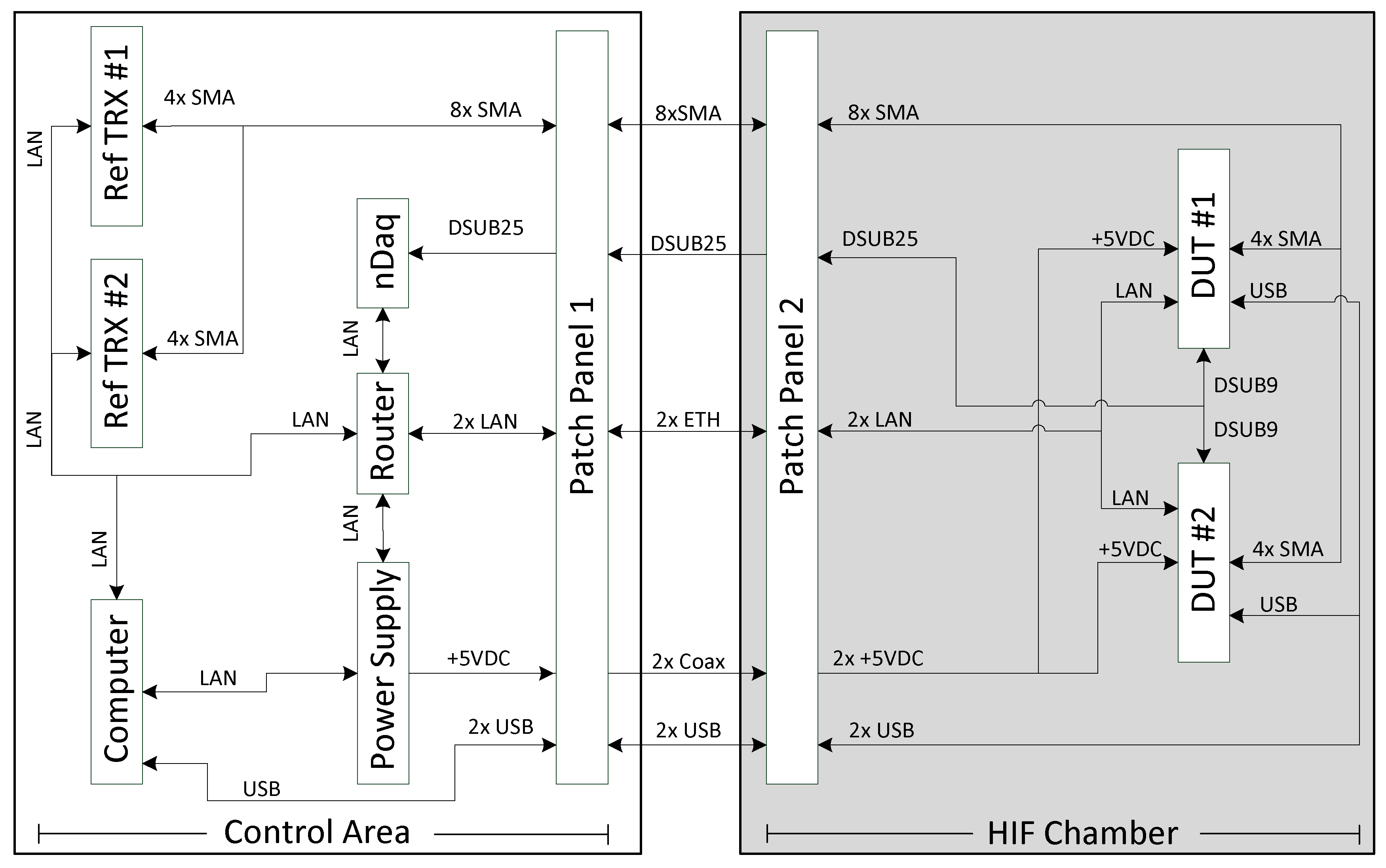
Aerospace Free Full Text Heavy Ion Induced Single Event Effects Characterization On An Rf Agile Transceiver For Flexible Multi Band Radio Systems In Newspace Avionics Html
System is out of lock and the frequency on IN is much higher than the frequency on IN.

. It may also have a divider in the feedback path or in the reference path or both in order to make the PLLs output signal. A new frequency-locked loop FLL similar to a PLL in the way that it generates an output signal which tracks an input. Compact Microwave Mercury Ion Clock for Deep-Space Applications We have recently.
Out with Hspice using the CMOS 035- m process shows that the. A digital phase locked loop uses a digital phase detector. 565 Phase-Locked Loop Block diagram explanation.
It can be used as a amplitude modulator product detector amplitude demodulator mixer frequency. The Phase Locked Loop. A control block diagram for the linearization model of the frequency extraction of the PLL disturbance components is given in Fig.
The block diagram of IC 565 includes a V CO in a feedback loop an amplifier a low pass filter. Phase pll simulink three. 9 Images about Activity.
Again references 1-3 provide thorough derivations of this method. A Phase Locked Loop abbreviated as PLL is a negative feedback system where an oscillator-generated signal is phase and frequency locked to a reference signal. The Phase Locked Loop.
The phase locked loop circuit of Figure 1 can be constructed in a control system block diagram form as shown in Figure 2. The error signal is then low-pass. PFD Waveforms Out of.
Phase-locked loop modeling. P072C Gearbox system locked in first gear P202B Short to ground in the tank. PLLs are used to.
Download scientific diagram Block Diagram of the frequency lock loop. Figure 5 is a diagram which shows the relevant waveforms. It is an automatic control system in which the phase of the.
The block diagram of a PLL operating as a frequency synthesizer is shown in Figure 1 8. Block diagram of LM565 PLL. Phase-locked Loop Block Diagram A phase detector compares two input signals and produces an error signal which is proportional to their phase difference.
The balanced modulator is an excellent building block for communication equipments.
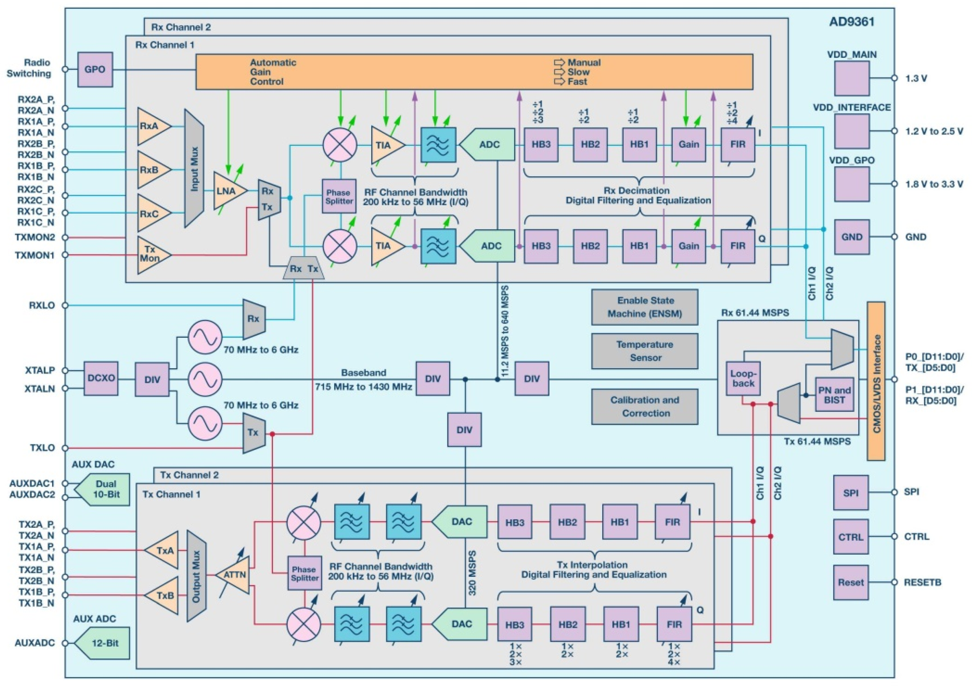
Aerospace Free Full Text Heavy Ion Induced Single Event Effects Characterization On An Rf Agile Transceiver For Flexible Multi Band Radio Systems In Newspace Avionics Html
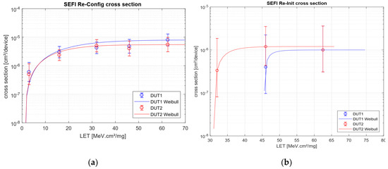
Aerospace Free Full Text Heavy Ion Induced Single Event Effects Characterization On An Rf Agile Transceiver For Flexible Multi Band Radio Systems In Newspace Avionics Html

Avr Atmega8 Board For Pll Mc145170 Electronic Schematics Pll Arduino
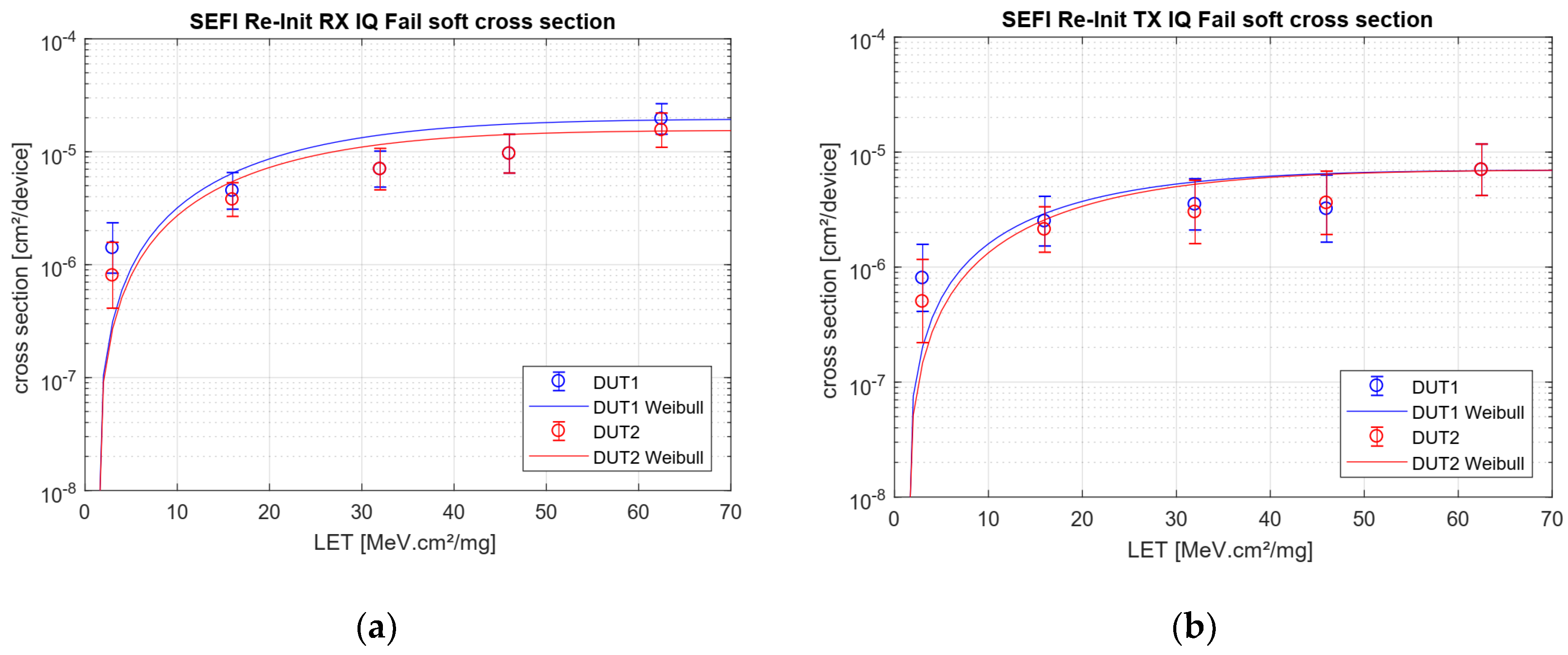
Aerospace Free Full Text Heavy Ion Induced Single Event Effects Characterization On An Rf Agile Transceiver For Flexible Multi Band Radio Systems In Newspace Avionics Html
2
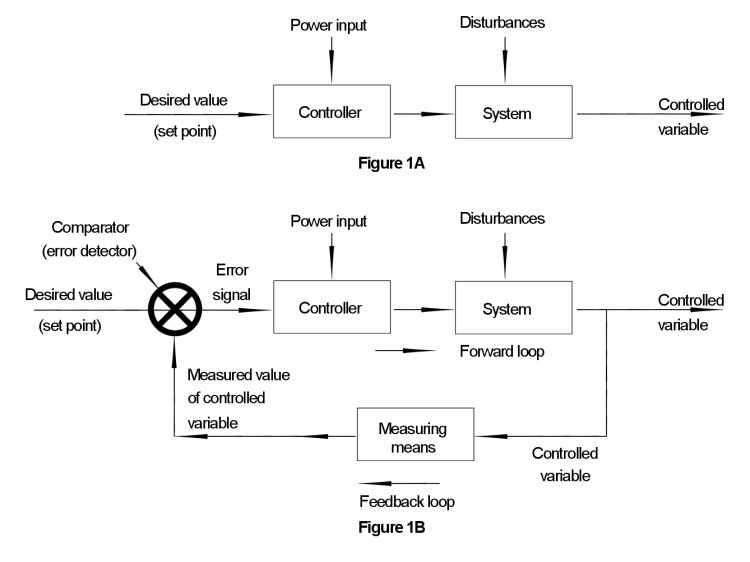
Open Loop And Closed Loop Systems

Ne567 Datasheet Tone Decoder Phase Locked Loop And Example Circuits Simple Electronics Function Generator Circuit
Why Is Pll Used In A Microcontroller Quora

Open Loop And Closed Loop Systems

Asdex Upgrade Sciencedirect
What Is Integrated Audio Codec Chip Quora

Operating Life Analysis Springerlink

Enhanced Top Down Protein Characterization With Electron Capture Dissociation And Cyclic Ion Mobility Spectrometry Analytical Chemistry

Ne567 Datasheet Tone Decoder Phase Locked Loop And Example Circuits Function Generator Circuit Simple Electronics
Why Is Pll Used In A Microcontroller Quora

Ne567 Datasheet Tone Decoder Phase Locked Loop And Example Circuits Simple Electronics Function Generator Circuit
Open Loop And Closed Loop Systems